Testing A Gm 3 Wire Alternator Wiring Diagram Description Gm 3 Wire
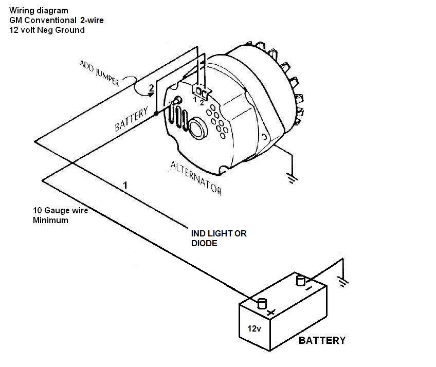
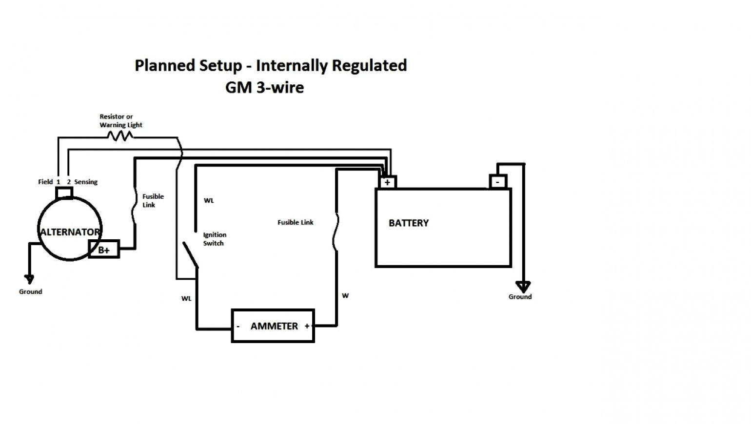
Wiring an alternator . This diagram shows how to wire a Delco (GM) internally regulated 3-wire alternator. This particular model (10SI, used in the 1970s and early 80s) is the one you'll find on the generation of GM cars most often used in demolition derbies. It was also used in a lot of off-road equipment, so they're generally cheap and easy.

Wiring Diagram For Car Alternator
Uncoil Cable The best approach to easily instal cables is to straighten them out there first. Pull typically the cable from the centre from the coils & lift a new handful of coils. Next thing is to toss them throughout the floor like you're throwing a coiled rope. When untangled, it helps in easier handling & neater storage. 3. Amperage Rating

Alternator Wiring Diagram 2 Wire
Alternator Voltage Regulation 101 (with Wiring Diagrams) - In The Garage with CarParts.com Learn how a car alternator works and find detailed alternator wiring diagrams, including for 3-wire connections in this article. Read on.
[DIAGRAM] Delco 1 Wire Alternator Diagram
The GM Alternator 3 Wire Diagram is an important document to have when working with the electrical systems in GM vehicles. This diagram provides a visual representation of how the alternator works and how it interacts with other components.. Gm 3 Wire Alternator In An 81. Wiring A Delco Gm Alternator. How Altenators Work Grumpys Performance.

Gm 3 Wire Alternator Wiring Diagram
In general, GM alternator wiring diagrams consist of three wires. The brown wire provides power to the alternator, while the black wire connects to the battery and serves as the ground connection. The red wire is the remote voltage sensing wire, which is used to regulate the output voltage of the alternator.
1986 chevy 350 alternator wiring
Bad Hombre Garage 4.85K subscribers 292K views 2 years ago In this episode I replace the old externally regulated and unreliable 12 volt GM alternator with a remanufactured Delco 10si GM.
[DIAGRAM] Chevy 1 Wire Alternator Diagram
The diagram will typically include components such as the regulator, starter, alternator, and battery. It will also include the wiring harnesses used to connect the components. Having a comprehensive GM alternator 3 wire diagram can be invaluable when troubleshooting electrical issues. It allows you to quickly identify the source of the problem.
96 Dodge Alternator Wiring Diagram
ALL MY VIDEOS are in 1080p so check that out..please use this video as a guide on hooking up a 3 wire GM alternator..alternator is a 55 amp from a 79 monte c.

3 Wire Alternator Wiring Diagram Dodge
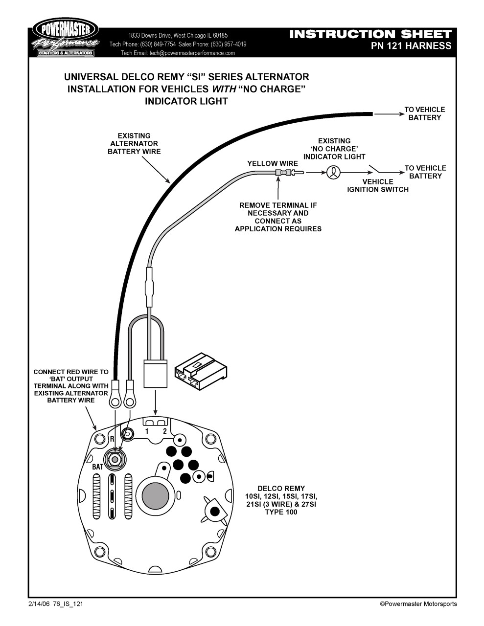
SHARE POST #1 recardo Member from Winslow On a three wire you have the #10 output wire. This goes to the junction of the starter and battery cable. On the clip, you have a #10 wire and a #16 (or so). Fold the #10 wire over and put a lug on it to connect to the same point as the output wire on the alternator.
2 Wire Alternator Wiring Diagram Wiring Diagram
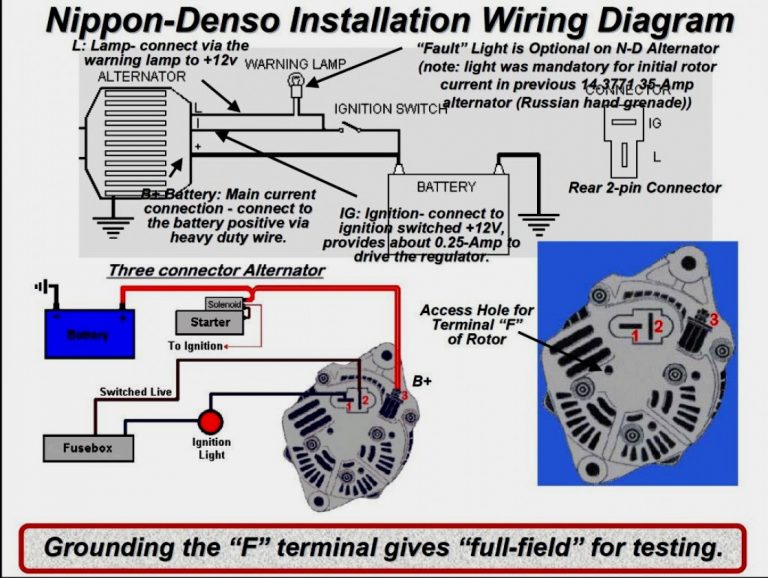
Running the ignition wire through a light bulb before connection to the alternator will give you a warning if your alternator fails to start charging or if it quits working while the engine is running, this is commonly known as the idiot light. Another thing that should be mentioned is the #1 terminal must be ignition switched.

Delco 3 Wire Alternator Wiring Diagram Free Wiring Diagram
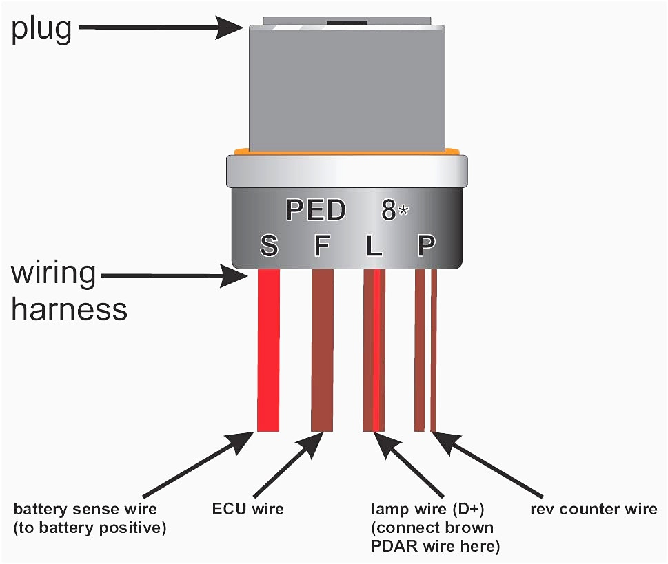
Understanding the 3-wire alternator wiring diagram is essential for automotive enthusiasts who are keen on working on their alternators. We then break down the basics of alternator wiring, its components, and the significance of each wire. The three main wires include the battery wire, field wire, and sensing wire.
Alternator Wiring Diagram Pdf
wiring up your GM 3 wire alternator and upgrading from externaly to internaly regulated Invincible Extremes Muscle Cars Garage 31.2K subscribers Subscribe Subscribed 105K views 6 years.
[DIAGRAM] Gm Cs130 Alternator 3 Wire Wiring Diagram
Get a short piece of wire with an adequate terminal plug on one end, and an o-ring on the other. Plug the wire into terminal 2, and place the o-ring side over the bolt, after the red wire. Tighten the bolt with a nut to connect the two o-rings with the alternator. Terminal 1 should be connected to the gen, battery, or alt dashboard light.
Wiring Diagram For Ford Alternator With Internal Regulator Wiring
In the realm of automotive wizardry, lies the enigmatic world of alternator wiring diagrams. And among them, the GM 3 wire alternator stands resolute. A captivating concoction of wires intricately woven, guiding the electrical symphony of your ride. Join us on this electrifying journey where we unravel the secrets of this marvel, decoding its mysterious language of power and efficiency. Brace.
Gm 3 1 Wiring Wiring Diagram 4 Wire Alternator Wiring Diagram
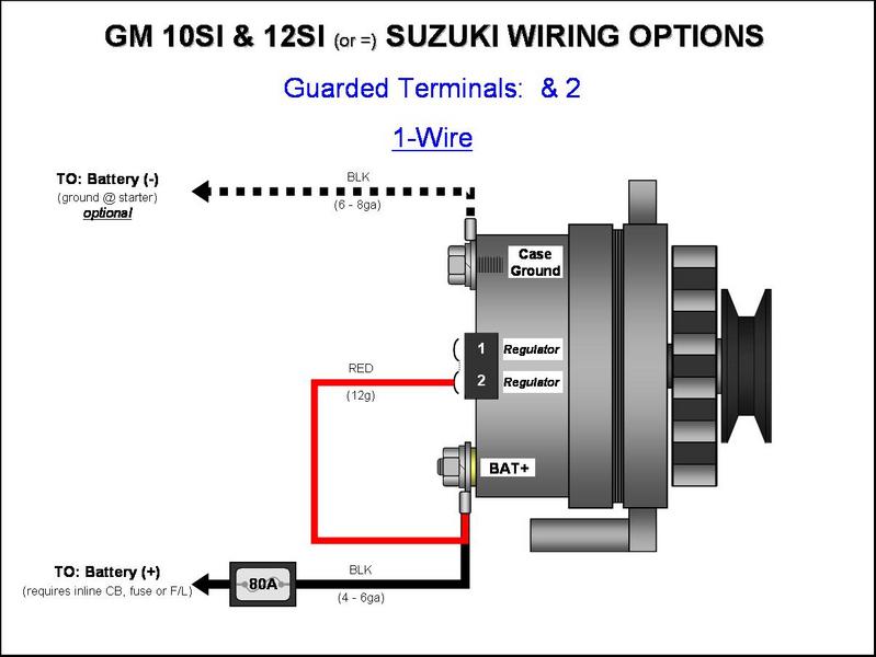
In the above diagram, the wire needed from the BATT on the rear of the alternator, to side terminal marked "2", does no0t have to end up being 40 feet long, nor go to anywhere else but directly from that BATT terminal on the back of the alternator, to the number 2 side terminal, 3 inches or so of 14 gauge wire and two terminals.
Gm 3 Wire Alternator Wiring Diagram Wiring Diagram
Not All Alternators Are Created Equal Late-model alternators are far more efficient at idle, so a stock 100-amp alternator might be capable of 60 to 65 amps at idle. But let's look a little closer. Alternator rating numbers are generally tested with the alternator at ambient temperature.